Knowledge base · Events
What the events on an OTDR trace mean
The curve drops in a step, jumps in a spike, or falls away into noise. Each of those shapes is an event, and the shape tells you what actually sits at that point of the fibre.
See the events in your own file
An event marks a place on the link. What to do about it depends on your project's requirements.
By Vera (new to the field) ·
Telling the kinds of event apart
What tells them apart is the shape of the curve, not the label in the table.
Reflective
A narrow spike upward, after which the level continues lower than before. That is the boundary between two media: a connector, a mechanical splice, an end face. The spike can be narrow enough that decimating the curve swallows it, which is why we draw the trace in a way that never can.
Non-reflective
A step down with no spike. A fusion splice or a bend: the medium does not change, but some of the light leaves. One trace cannot tell a splice from a bend, because a bend costs more at the longer wavelength, and that only shows if 1310 and 1550 nm are laid side by side.
A ghost
A reflection that is not in the fibre at all: the light reflected twice, and the instrument drew an event at double the distance. The sign is a distance that is a multiple of the distance to a strong reflector, with no loss at it. The guess can be checked on the spot: if the ghost is thrown by the reflection off the far end face, wind that end onto a mandrel for a few turns. The reflection dies, and the ghost goes with it.
A ghost has a second source as well: a range set too short. If the acquisition range is shorter than the line, the instrument fires the next pulse before the reflection from the far end has come back, and that reflection lands in the new trace. The false peak then sits not at a multiple of a distance but at a difference: a 25 km line measured on a 20 km range shows it at about 5 km. The end of such a trace gives it away too. The trace stops where the range stops, with no end-face reflection and no noise after it. The cure is to measure again on a range comfortably longer than the line.
The fibre end, and what lies past it
The end is where the curve breaks into noise, usually with a strong reflection off the end face. Everything drawn beyond it is not fibre but receiver noise, and events there mean nothing. The only reason to look there is to check the length: if the end turned up well short of the designed length, the measurement caught the wrong span, or a break.
Splice closures, patch panels and splitters on a trace
An OTDR does not know what is installed on the link: it sees a step, a spike or light being divided. Closures, patch panels and splitters are found on almost every link, and each has its own shape.
Splice closure
The closure itself does not show on the trace, only the splices inside it. Each one is a step down with no spike. If the fibre is coiled too tightly in the splice tray, a bend adds to the splice, and the step is then noticeably deeper at 1550 nm than at 1310 nm. A spike where the closure sits means there is a mechanical splice or a connector there rather than a fusion splice.
Patch panel (ODF)
A patch panel is made of connectors, so on the trace it shows as a spike with a step after it. Often a pigtail splice and the connector on the adapter sit a few metres apart there, and the instrument records them as one merged row. A patch panel right next to the instrument hides in the dead zone and can only be measured through a launch cable. An unusually strong spike at a patch panel most often means a dirty or damaged end face.
Splitter
A splitter usually gives the deepest step on the link, and its depth is set mainly by the number of branches: the light is divided between them. Seen from the OLT side, the trace after a splitter is the sum of all the branches at once, so events behind it overlap and there can be several fibre ends. How to read such a trace and how much a splitter of each ratio takes is covered in the PON guide.
The words "closure" and "patch panel" are not in the trace. They come from the link diagram, which is what each step is matched against. The match is made by distance, and it needs a correction. An OTDR measures fibre length, which is longer than the cable because of how the fibre lies in the tube, and it also includes the cable slack left at closures and in manholes. So on the trace a closure sits further away than on the diagram, and the gap grows with distance from the start. Why one link has several lengths is covered in the guide on three lengths.
If the diagram shows a closure and there is no step at that spot, it is usually a good splice below the detection threshold, not a missing closure.
Why our list differs from the instrument's
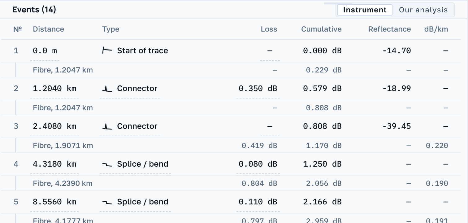
The instrument stores the events its own detector found, at its own threshold settings. We search again and show both lists, marking who found each event: the instrument, us, or both. They often disagree, because the thresholds differ. Neither list overrules the other, and comparing them by eye is usually why the file was opened.
How much that changes is shown by a picture in the EXFO manual: the same fibre acquired three times, with the threshold at 0.05, 0.1 and 0.15 dB. At 0.05 both splices are in the table, at 0.1 only the first, at 0.15 none of them. The fibre was the same throughout; only a setting on the instrument changed. So when one file gives two instruments different event counts, the usual reason is the threshold rather than one detector being worse than the other. What that threshold is and where it sits in the file is covered in the guide to detection thresholds.
On ghosts in particular: it is the person who recognises them, not a label in the file. Ghost is our own word for such an event and it stays in our prose; the row of the table carries the INSTRUMENT's word, and that differs between makers. EXFO calls it an echo and keeps two cases apart (an echo past the end of the fibre, and a possible echo at a multiple of a distance), writing them as a flag inside the file rather than as a word: our corpus carries 247 such rows. IIT instruments write words into the event's own text field: "Possibly doubled reflection". We show that as it stands, adding nothing and translating nothing. Where the instrument said nothing there is no name at all. What to trust there is not a name but the two signs from the card above: a distance that is a multiple, and no loss at the event.
A word about gainers. Sometimes the instrument records a negative loss at an event and marks the row with its own word, gainer. No light was added at the joint. Two fibres with different backscatter coefficients are spliced together, and from one end the trace rises where from the other end it would fall. The vendor says as much about these rows: the printed loss is not the real one, and the real one comes from averaging the two directions. We say the same thing twice: the instrument's word with its tooltip in the row, and a caveat under the table that counts such events across the whole document. How the two directions are measured is covered in the guide to bidirectional testing.
The event table is edited on the instrument itself
In the instrument's own manual, editing the table is ordinary operator work, not an emergency mode. You put the marker where the event belongs and press add; you select a spurious row and delete it; you open a row for modification, place the splice-loss markers by hand and accept the result. The same screen is where the operator marks the start and the end of the fibre being handed over: the span is set by hand, so that the launch cable does not count towards the total.
The file itself never shows it, but a row in the table was not necessarily found by a detector. Some events may have been placed by a person, others re-measured by hand, and .sor has no field that tells the two apart. We mark who found each event (the instrument, us, or both), but here "the instrument" means "came with the file", not "found automatically".
The same instrument has a second screen where the line is drawn as a diagram: every event is given a kind, splice, connector, angled connector, bend or splitter. It is given by a rule over two numbers, loss and reflectance, and the rule's thresholds sit in the instrument's settings. That is a conclusion drawn from a measurement, not a measurement; and it does not travel in the file. By the manual, the traces of a group are saved into one folder and the diagram is built over them. So the picture the customer saw from the contractor may have no footing in any byte of the .sor they were sent.
How an event type gets lost on the way to the customer
An event type looks like an objective property of the file, but it is the instrument's statement, and it does not always reach the customer intact. In the VIAVI SmartOTDR firmware, the handover-package builder collapses four classes into one before export: Reflection, Fiber End, First Connector and Link all become Connector. In that package the fibre end can no longer be told from a connector, and the word the instrument wrote is not shown at all. The instrument's own maker does this on its own format, and does it deliberately, to fit the receiving system's vocabulary.
This explains the question an acceptance engineer asks first: why the event type in the report and in the file disagree. It also explains our rule. The class belongs to the instrument, we print it in the source's own word and rewrite it neither on screen nor on export; an edit made by hand goes into the journal inside the file itself. That way the word the instrument wrote stays whole in the file.
What the file never carries
A row in the table is not always one event. Where two joints stand too close together, the instrument writes them as a single row, and some instruments admit it: such a row is marked as merged. Nothing can separate it afterwards, including the instrument that recorded it. How close that is can be read off our corpus: the median gap between adjacent components is 5.26 m, which is to say connector pairs and short patch cords. The loss in such a row belongs to the group as a whole and the reflectance to its strongest component; why it comes out that way is in the guide to the dead zone.
The second limit runs along the list of kinds itself. On a VIAVI instrument the operator picks the kind by hand out of eight: a splice, a connector, an expanded-beam connector, a balanced splitter with its ratio, an unbalanced tap with its ratio, a ghost, Mux/Demux, and the end of the fibre. What reaches us is whatever the instrument wrote into the file, and that comes to four classes in the instrument's own word. Neither the expanded-beam connector nor the tap is among them, and neither can be added: a kind enters our list when the instrument writes it into a file, not when its own interface shows it.
A kind that was not in the file will not appear on the screen, even if the operator knew it while standing at the instrument. That is why a row can say "reflective" where a splitter stands on the line. Bend is in no generation's assignable list at all: instruments only detect it. That is why our own bend label lives in the experimental mode, signed as our inference.
Next
We run one detector for every instrument's files. Behaviour never branches on the model name in the header, because that field is edited by hand, and a branch on it would send a file down the wrong path.