Knowledge base · Acceptance
Where "within limits" comes from: acceptance thresholds
The verdict column in the event table is not always there. It appears once at least one limit is set: there is no verdict without a limit, and you write the limit; the program sets none of its own.
Check your file against your own limits
People use the word "threshold" for two different things. Whether an event reaches the table at all depends on the detection threshold; whether what did reach it is good enough depends on the acceptance limit. This page is about the second.
By Ilya (engineer, 6 years in fibre optics) ·
Which figures are held to limits
There is never just one figure: the fibre and the joints each have their own numbers, and a limit written about a fusion splice says nothing about a connector.
Event loss
How much one joint loses. A specification usually states a single figure for every event, which is how most instruments' thresholds are shaped too. Where splices and connectors are stated separately, each gets its own limit: a fusion splice and two mated end faces cost different things by construction. What tells them apart is the event type the instrument recorded, not our guess about what stands there.
Reflectance
How much light came back from the joint. This limit reads the other way round: the figure is negative, and "no worse than" means "further from zero". A fusion splice has little to reflect with, so for many rows of the table the file carries no such measurement at all, and the limit is not applied to them.
The whole link
The attenuation of the fibre itself on a section between events, the loss end to end, and the optical return loss of the whole link. These are the numbers copied into the acceptance document, and they live apart from the rows: every joint can pass its own limit while the sum does not fit.
An instrument has many thresholds; few reach the document
Vendor software shows this well. An instrument's threshold page is large: slope stated separately for each wavelength band, an upper and a lower bound on total loss and on span length, separate thresholds for splitters and taps, a separate pair for expanded-beam connectors, more than twenty figures in all.
The same vendor's acceptance-package generator carries four of them outward: splice loss, connector loss, reflectance, and the fibre's optical return loss. Between the screen in the field and the file that goes to the customer the list contracts because the contract was written about these four; the rest does not stop mattering because of it.
The list of limits you need comes from the document you are handing over; neither the program nor the instrument decides it. Our screen does not stop you writing any limit of yours, and it writes none for you.
The same document also determines which instrument you measure with. The TIA-568 cabling standard requires link attenuation to be measured with a light source and power meter, and adds the OTDR as a second, optional tier of testing. On single-mode the two methods show no systematic gap. On multimode an OTDR on the same link reads lower: judged by backscattered light, a joint with offset cores comes out lighter than it is for light passing straight through. How much lower depends on the instrument, so there is no figure here either. A link-loss limit taken from such a document was written for the meter's figure, and passing it on a multimode trace does not yet promise that the link will pass acceptance.
What our screen does once a limit is set
Limits live on the Limits tab next to the file's settings. As soon as one limit for rows is set, the Verdict column appears in the event table. There is no column of dashes: while no limits are set the table simply has one column fewer, and the room goes to what was measured.
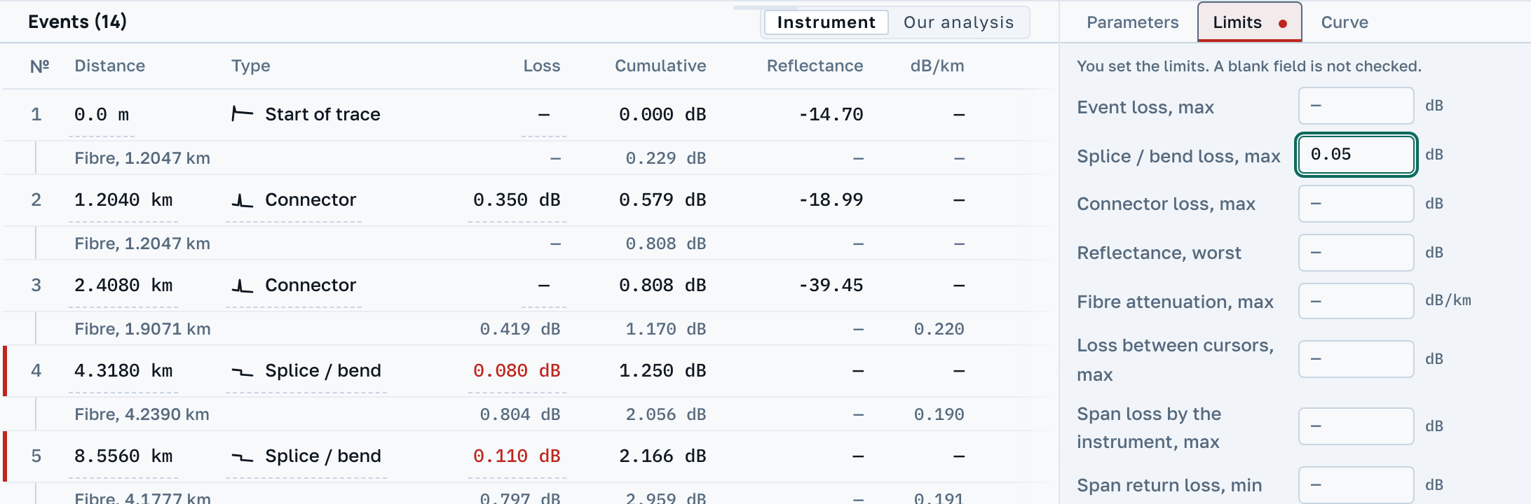
One limit does not raise that column: Loss between cursors, max. It applies to the stretch between the cursors rather than to a row: every row would carry a dash under it, and its answer is printed where that stretch itself lives.
Where a limit that was set has nothing to be applied to, the row stays without a verdict and says so in words. There are two reasons for that. The instrument recorded no such figure at all, so there is nothing to check. Or the receiver saturated: a reflectance is printed in the cell, but it is a floor on how strong the reflection is rather than a measurement of it, so a breach of the limit counts and "within limits" does not. The same sentence stands on a row that passed, when it passed on one of the two limits set for it: half of what was asked went unasked, and knowing that matters more than seeing green.
A figure the file does not carry is not judged at all. A zero in the loss field and an empty reflectance field mean "not recorded", not "zero" and not "the worst there is"; a dash stands in their place in the table. Otherwise one reflectance limit would fail every fusion splice on the trace at once, and a loss limit would pass them all just as blindly.
You will not find a single normative value here
The page is called "thresholds", and most people arrive at it for exactly one thing: the number. There will be no number. How much a fusion splice may lose is decided by the project, by a standard, or by the customer's requirements, and those differ by country, by cable and by contract. A value invented by a program would be read as normative by precisely the reader least able to check it.
A blank field means "not asked": it is not checked, so it cannot have passed. So about a file with no limits set we say neither "within limits" nor "outside limits"; we say that nothing was checked.
We name our own bounds. A limit here belongs to the document, not to a wavelength: there is one set of them, not one per wavelength. There is no limit on span length and none on the link's optical return loss. There is no amber "only just passed" either; there are two verdicts. If you need a vendor instrument's list of thresholds reproduced one for one, that is not us yet.
Next
A pair of traces shot from both ends is checked against the mean loss of the two directions rather than against one of them: at a joint between two dissimilar fibres the one-way figure is overstated at one end and understated at the other by exactly the same amount.