Knowledge base · What is this on my trace
Short fibre on an OTDR: why the start of the trace shows nothing
An OTDR can test a short link if the pulse is short and a launch cable stands in front of the link. After every pulse the receiver is blind for a while. With a long pulse that blind stretch can be longer than the link itself, and the trace draws a flat line where the fibre is.
Check the pulse width in your file
By Ilya (engineer, 6 years in fibre optics) ·
On this page
What it looks like
Below is one multimode cable from the FOA training set, measured four times at 850 nm. Only the pulse width changed between the shots: 30, 90, 330 and 1000 ns. At 30 ns the curve comes off the top of the scale after 12 m and shows two connections, at 235 m and 464 m. At 1000 ns the curve lies flat at the top of the scale for the first 1271 m, and both connections are inside that stretch.
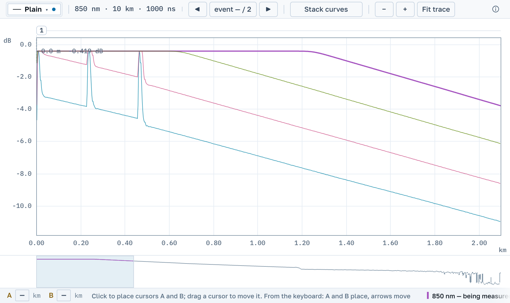
| Pulse width | The curve lies flat for the first |
|---|---|
| 30 ns | 12 m |
| 90 ns | 31 m |
| 330 ns | 669 m |
| 1000 ns | 1271 m |
The figures are read off the curves of this instrument and this cable, at a sampling step of 3 m. Another instrument gives other figures.
Why the start is blind
The instrument sends a pulse and listens for the weak light the fibre scatters back. The reflection from its own connector is much stronger than that scatter. According to the FOA reference guide, the test pulse overloads the receiver and leaves a dead zone next to the instrument.
A. V. Listvin and V. N. Listvin write in «Рефлектометрия оптических волокон» that the dead zone at the input is the widest one on the trace, and that a flat top on a peak means a saturated receiver. The flat stretch in the picture above is such a top, hundreds of metres long.
The longer the pulse, the longer the receiver stays blind. The same FOA guide says an OTDR works best on cables longer than about 250 m, and that premises cabling is tested with the shortest pulse the instrument has.
A dirty instrument connector widens the blind start
A bad launch gives the same picture even with a short pulse. The Listvins' book names two signs that come together: the whole trace sits lower than with a good connection, and the dead zone at the input is several times wider. The cause is a dirty or damaged connector on the instrument or on the cord plugged into it. Less light enters the fibre, and the stronger reflection at the input blinds the receiver for longer.
One file cannot tell a bad launch from the normal behaviour of the instrument. Compare the start with a trace taken by the same instrument at the same pulse width. The book advises cleaning the connectors, using a test cord so that the instrument port does not wear, and putting a launch cable in front of the link.
What to do about it
- Set the shortest pulse the instrument offers. For fibres of 300 to 500 m FOA advises the shortest pulse, a range of about 1 km and enough averaging to bring the noise down.
- Put a launch cable between the instrument and the link. A test cord of 1.5 m is not a launch cable, FOA says in the same answer. As a minimum for short cables it names 10 to 20 m on multimode and 100 m on singlemode.
- Look at the pulse width before judging the link. In automatic mode the instrument picks the pulse itself, and it picks a longer one for a longer range.
- Read the loss of a short link with care. It is small, and FOA notes that the uncertainty of an OTDR measurement is higher over short distances.
What OTDR Master shows
Open the file and find the Pulse width row among the measurement parameters. It holds the pulse the trace was shot with. If the first event stands closer to the start than the pulse is long in the fibre, a line under the table says that the event sits inside the dead zone of the pulse and that its loss was measured neither by the instrument nor by us.
Open several shots of one fibre together and the curves are drawn on one chart, as in the picture above. A short-pulse trace laid over a long-pulse one shows what the long pulse covered.
Where this stops
We do not restore what the instrument did not record. Inside the flat stretch the file holds the same level sample after sample, and no analysis will find a connection there. Our own event analysis looks for nothing in the first metres of the trace either. The start of a short link can be seen only after a new shot, with a shorter pulse or through a launch cable.
Sources
- The Fiber Optic Association. The FOA Reference For Fiber Optics: Optical Time Domain Reflectometer (OTDR).
- The Fiber Optic Association. FOA Newsletter, October 2018. Q&A: OTDR Setup. 2018.
- А. В. Листвин, В. Н. Листвин. Рефлектометрия оптических волокон. М.: ЛЕСАРарт, 2005.