Knowledge base · What is this on my trace
A step that is bigger at 1550 nm than at 1310 nm is a bend
A splice and a bend look the same on one trace, a step down with no spike. They differ at a second wavelength. A splice loses about the same at 1310 and 1550 nm, and a bend loses several times more at the longer one.
Compare two wavelengths of your own fibre
By Ilya (engineer, 6 years in fibre optics) ·
On this page
What it looks like
Below is a demonstration trace from the EXFO sample set: one fibre of 37 km measured at 1310, 1550 and 1625 nm and drawn together. The table lists four steps without reflection. Three of them are the same size at every wavelength. The one at 25 km reads 0.100 dB at 1310 nm, 0.699 dB at 1550 nm and 1.299 dB at 1625 nm.
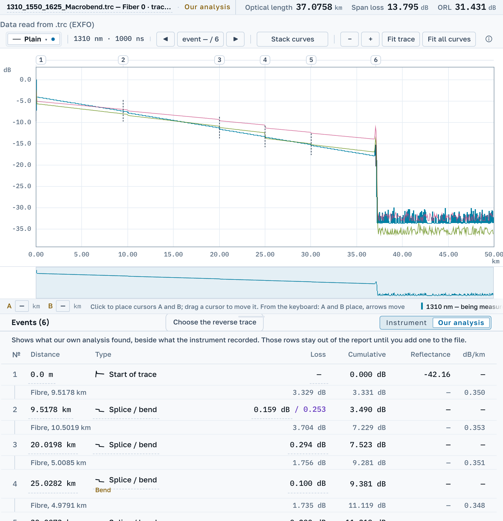
The splice at 30 km, for comparison, reads 0.200, 0.197 and 0.201 dB.
Why a bend depends on the wavelength
In a bent fibre part of the light leaves the core, and the longer the wavelength, the more of it leaves. A. V. Listvin and V. N. Listvin write in «Рефлектометрия оптических волокон» that bend loss grows with wavelength much faster than any other loss in the line. A splice, a connector and the fibre itself change little between 1310 and 1550 nm.
Instrument makers use the same test. The EXFO user guide for the FTB-7000 series calls an event a macrobend when the greater loss is at the greater wavelength and the difference is above a set value, 0.5 dB by default. It also recommends comparing the shortest and the longest wavelength available. On this trace the step at 1625 nm is almost twice the step at 1550 nm.
Bends are most often found in a splice closure, where the fibre is coiled next to the splice, and in a cabinet where patch cords are laid, the same book notes. The bend and the splice then stand closer than the instrument can resolve, and the table shows them as one event.
What to do about it
- Measure the fibre at a second wavelength before deciding anything. One trace cannot tell a bend from a splice.
- If the step grows with the wavelength, do not redo the splice. Open the closure or the cabinet and re-lay the fibre.
- If the step is the same at both wavelengths, it is a splice or a connector, and re-laying will not help.
- If the whole trace falls more steeply at 1550 nm than at 1310 nm, suspect bending spread along the cable and look at how the cable was laid.
What OTDR Master shows
Open the same fibre at two or three wavelengths and the curves are drawn together. Switch the table to Our analysis. An event that loses materially more at the longer wavelength gets the label Bend next to the type the instrument recorded, and a line under the table names the two wavelengths that were compared.
We compare the shortest and the longest wavelength on the chart. Only events found at both wavelengths are compared, and reflective events are left out.
Where this stops
On multimode fibre we do not make this comparison, because the rule was measured on singlemode. An event the instrument did not record at one of the wavelengths gets no label: a missing row means the instrument threshold was not reached, which is different from a measured loss of zero. The label belongs to the view. It is not written into the file and does not go into the report.
Sources
- А. В. Листвин, В. Н. Листвин. Рефлектометрия оптических волокон. М.: ЛЕСАРарт, 2005.
- EXFO. FTB-7000 Series, OTDR for FTB-200. User Guide. Version 11.0.3, 2009.